A PDF drawing and a CAD file arrive in the same package. Both represent the same part. One was updated last week. The other wasn’t.
Nobody knows which one is current until the machined part fails inspection.
That gap, between what the 3D model shows and what the 2D drawing says, is one of the most consistently underestimated cost risks in custom manufacturing. Teams rarely detect it during quoting, and programming workflows often carry it forward unnoticed. By the time the discrepancy surfaces during inspection, delivery, or a supplier dispute, the cost of correction can be several times higher than the cost of catching it earlier.
A parts manufacturer described it precisely. Customer PDFs arrive with CAD files alongside them. Both files are supposed to tell the same story. When a tolerance gets updated in the model without making it into the drawing, or a feature exists in the 3D geometry but not the 2D annotation, nobody catches the gap until production is underway. By then, the damage is already built into the schedule and the cost.
In most cases, the gap isn’t obvious. The PDF looks current. The CAD file looks current. The discrepancy lives in the space between them — a tolerance tightened in the 3D model that didn’t make it into the 2D annotation, or a feature added to the geometry that the drawing notes never caught up with. It’s not visible until someone acts on the wrong version.
This blog breaks down where engineering drawing discrepancies come from, where they hurt most, and what changes when AI compares both files before the job reaches the floor.
When the PDF and the CAD File Tell Different Stories
In most manufacturing workflows, engineering teams work across two formats. The CAD file, STEP, DWG, or native, holds the 3D geometry. The PDF carries the annotations, tolerances, and title block in a format everyone can open and read. Both travel with the job. Both are used at different stages.
The assumption is that they match.
They don’t always.
CAD files and PDF drawings drift apart for predictable reasons. A designer updates the 3D model but doesn’t regenerate the 2D drawing before sending the package. A revision gets made to the PDF annotation without touching the underlying geometry. A tolerance gets tightened in one file and not in the other. Across multiple revision cycles, the gap between what the CAD file shows and what the PDF says widens without anyone noticing — because nobody directly compares the two.
When a 2D drawing and a 3D CAD model don’t agree — mismatched dimensions, missing features, outdated revisions — the person programming the job works from whichever file is in front of them. If it’s the wrong one, the toolpath is wrong. The part comes off the machine. Inspection fails.
For a closer look at how drawing errors compound into BOM failures before quoting even starts, see our post on engineering BOM errors.
How Engineering Drawing Discrepancies Actually Enter the Workflow
The discrepancy doesn’t cause a problem the moment it exists. It causes a problem the moment someone acts on the wrong version.
That happens at three points.
At quoting
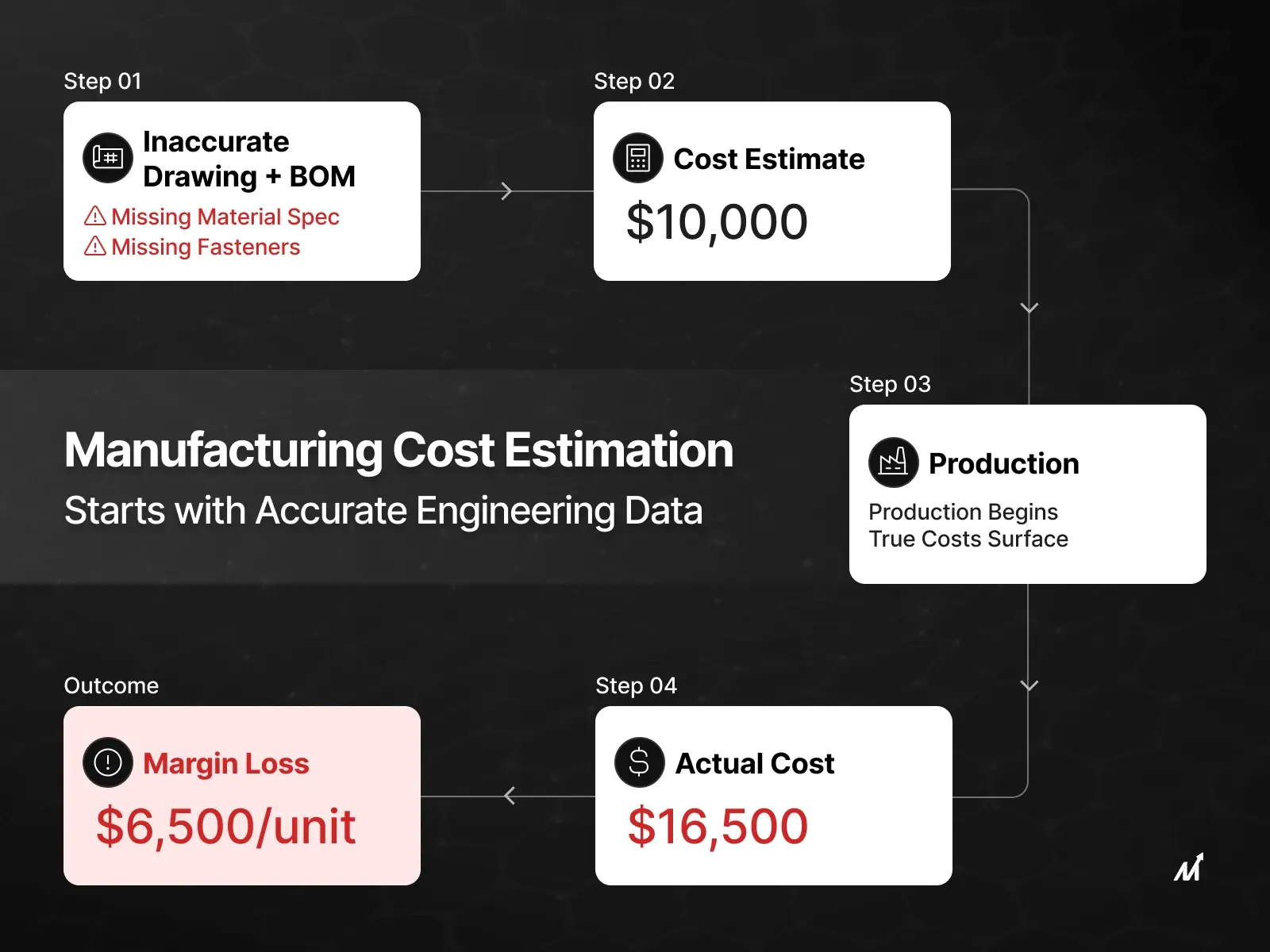
The estimator builds a cost model from the drawing. If the PDF and the CAD file disagree on a critical dimension or tolerance, the estimator prices one version while the supplier machines the other. The quote reflects a part that doesn’t match what production will actually require. That gap shows up as margin loss after the job is won, not before. Read more about how BOM discrepancies from drawing misreads create downstream cost problems that compound at every stage.
At programming
The CNC programmer works from whichever file is in front of them — often the PDF, because it’s easier to read. If the PDF doesn’t reflect the current CAD geometry, the toolpath gets written to outdated specifications. The program runs. The part comes off the machine. Inspection fails.
At inspection
Quality teams inspect against the drawing. If the drawing and the model disagree, inspection can pass something that doesn’t conform to the actual design intent, or fail something that does. Either outcome wastes time and creates problems that are expensive to trace back to where they started.
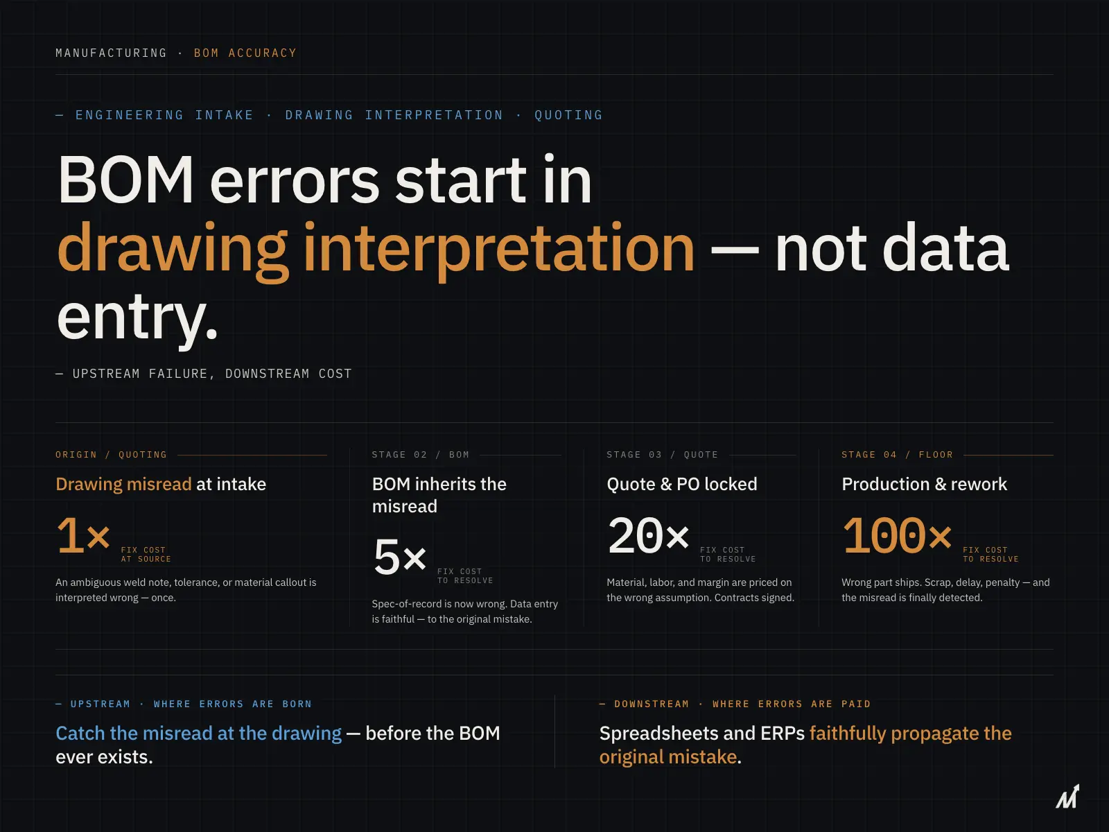
Missing tolerances, ambiguous notes, incorrect callouts — none of these announce themselves as errors when the drawing is read. They announce themselves as scrap, rework, and schedule delays when the part comes back from the floor.
Where the Cost Surfaces — And Why It’s Always Later Than It Should Be
A discrepancy caught before quoting costs nothing. Someone updates the file, the quote goes out correctly, and the job runs cleanly.
Caught at programming — it’s a revision cycle. Updated toolpaths, additional review time, delayed production start.
Caught at inspection — parts already machined need rework or scrap.
Caught after delivery — a customer quality dispute and a corrective action report.
The cost isn’t fixed. It grows at every stage. Each stage builds on the assumption that the drawing is correct. Once that assumption proves wrong, every decision made downstream of it needs revisiting, and the later that happens, the more expensive the correction. Industry data consistently shows that rework from incorrect drawing details costs US manufacturers billions annually, and the further downstream an error travels before it’s caught, the more expensive the correction becomes. The later the catch, the higher the price.
For more on how the cost of drawing errors escalates through production, see our post on manufacturing cost estimation.
Why Manual Drawing Review Misses What Matters Most
The standard response to drawing discrepancies is a review; someone checks the PDF against the CAD file before the job goes to the floor. In principle, that works.
In practice, it breaks down in three ways.
It depends on who does the review
An experienced engineer reading both files catches a tolerance mismatch that a less experienced reviewer misses. On high-volume RFQ operations where every job brings a different drawing package, consistent review quality is hard to maintain.
It doesn’t scale
Reviewing a single-sheet PDF against one CAD file is manageable. Reviewing a 20-sheet drawing package across multiple CAD files — where callouts on sheet 6 reference geometry that only appears in the 3D model — takes significant time. Under deadline pressure, the review gets shortened. The parts that don’t get checked are where the discrepancy hides.
It misses cross-file relationships
A PDF drawing and a CAD model aren’t just two views of the same part. They carry different types of information that need to be read together. A dimension on the PDF may reference a datum that only exists in the 3D geometry. A tolerance note in the CAD file may not appear anywhere in the PDF. Manual review done page by page misses the connections between files where discrepancies most commonly hide.
The gap between a CAD file and its PDF doesn’t appear when the files are created. It appears when someone downstream uses one of them to make a decision — and that decision turns out to be based on the wrong version.
Learn more about how engineering drawing revision control failures compound the discrepancy problem across revision cycles.
How AI Catches Engineering Drawing Discrepancies Before They Reach Production
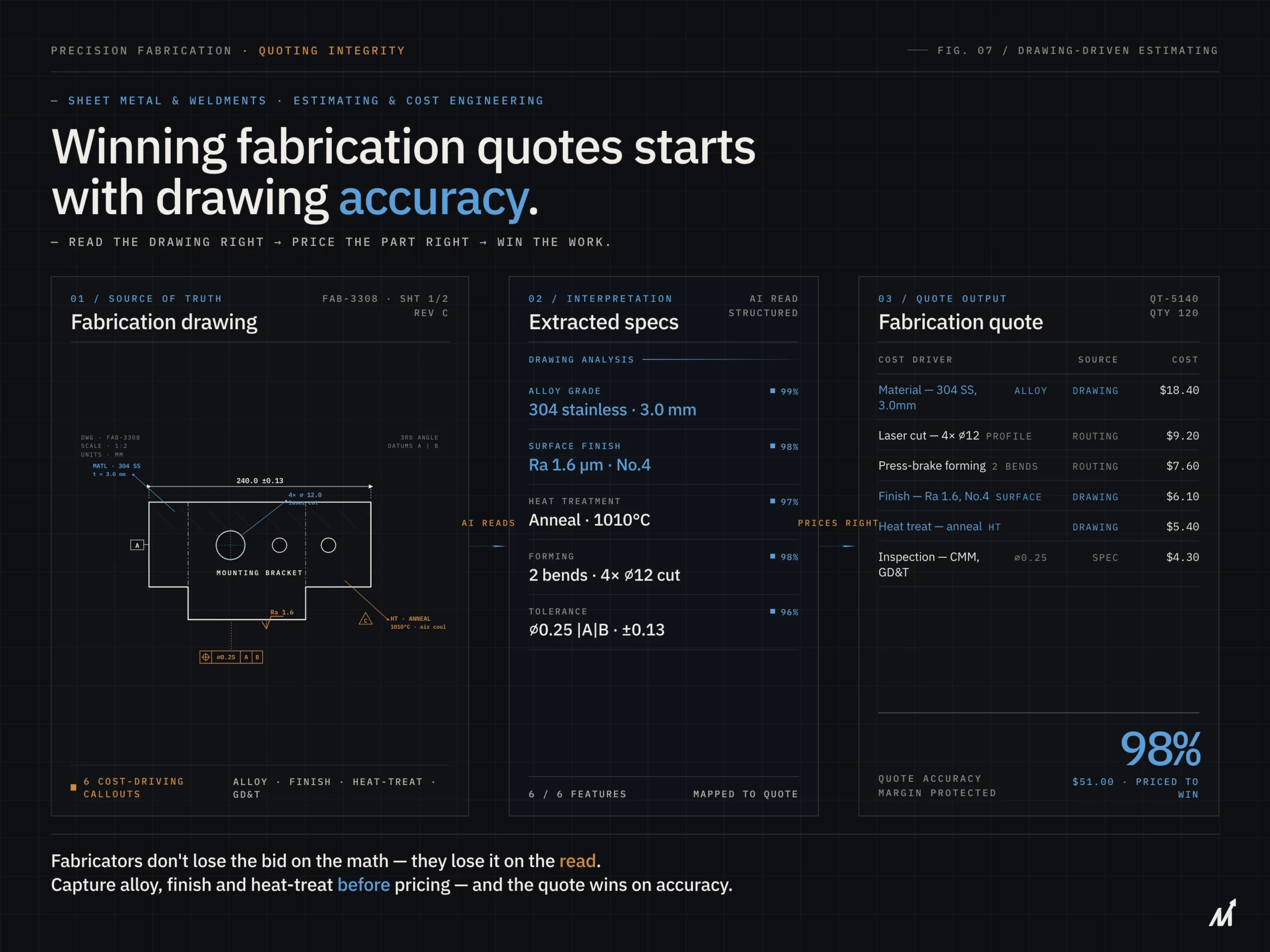
AI approaches drawing comparison differently from manual review — not because it’s faster, but because it reads both files at the same time rather than one after another.
When a drawing package arrives containing a 2D PDF and a 3D CAD file, AI analyzes both as a connected dataset. It compares dimensions, features, and tolerances across the two files to uncover discrepancies that manual reviews often miss. The system also traces references across revisions and detects notes that point to geometry changed earlier in the CAD model.
That comparison doesn’t depend on an experienced reviewer having the right files open in the right order. It happens on every package, on every job, with the same consistency regardless of volume or deadline pressure.
The output isn’t a general alert that something needs checking. It’s a specific, cited report — exactly where the discrepancy is, what the PDF shows, what the CAD file shows, and what the difference means for the job. Engineering teams get actionable information rather than another task on the review list.
For operations receiving STEP, DWG, and PDF files in the same package, our engineering intelligence platform accepts all three formats natively. The comparison happens at the geometry level — not the document level.
For a closer look at how AI reads engineering drawings differently from standard document tools, see our post on AI-powered blueprint interpretation.
How Markovate Closes the Gap Between Your CAD File and Your PDF Drawing
Manufacturing teams that receive drawing packages in mixed formats — PDF, STEP, DWG, DXF — carry a consistent operational risk. The gap between what the 2D drawing shows and what the 3D model contains doesn’t show up on a dashboard. It doesn’t generate an alert. It shows up as a rework charge, a missed inspection, or a customer quality dispute after the job is done.
In our experience processing engineering drawing packages across manufacturing verticals, the most common discrepancy type is tolerance updates that appear in the 3D model but don’t make it into the 2D PDF title block or drawing notes. These are the discrepancies that manual review misses most consistently — because they require reading both files together, not sequentially. Here enters one of the best AI platforms.
Our Product: AI Blueprint Classifier
Markovate’s AI Blueprint Classifier, powered by CADIAM™, addresses this before quoting, before programming, before inspection. Our platform reads 2D PDF drawings and 3D CAD files together — comparing dimensional data, tolerance callouts, feature geometry, and revision information across both formats simultaneously. When a discrepancy exists between what the PDF says and what the CAD file shows, the system surfaces it with a specific, cited output. Engineering teams know exactly what to review and where — rather than spending hours on a full manual check that may or may not catch the right things.
For operations managing high volumes of custom jobs where every package arrives in a different format combination, consistency matters. Every package gets the same comparison. Every discrepancy gets flagged before it enters the cost model or the production schedule.
As a U.S.-based mid-sized manufacturer producing hundreds of millions of precision parts annually, put it: “Markovate’s AI Blueprint Classifier helped us significantly accelerate our cost and timeline estimations. The automation and accuracy it brought to blueprint analysis have become a major value-add to our pre-production process.”
Book a demo at blueprintclassifier.ai to see how drawing comparisons works on your actual packages.
The Discrepancy You Don’t Catch Is the One That Costs You
Drawing discrepancies don’t fail silently. They fail loudly, at the worst possible moment, at the highest possible cost.
The PDF and the CAD file should tell the same story. When they don’t, every decision built on either one carries the same flaw, through quoting, through programming, through inspection, until something on the shop floor forces the error into the open.
Catching it early is cheaper. Catching it automatically, on every package, is how manufacturing teams stop paying for the same problem repeatedly.
FAQs: Engineering Drawing Discrepancies
1. What causes discrepancies between CAD files and PDF drawings in manufacturing?
The most common cause is revision cycle lag — the 3D CAD model gets updated, but the 2D PDF drawing doesn’t get regenerated before the package is sent. Over multiple revision cycles, tolerances, features, and annotations in one file stop matching the others. Because nobody directly compares both files at each stage, the discrepancy travels undetected until someone acts on the wrong version
2. At what point in manufacturing do CAD-PDF discrepancies cause the most damage?
The most damage happens at inspection or post-delivery, when parts are already machined or shipped. A discrepancy caught before quoting costs nothing. The same discrepancy caught at inspection means rework or scrap. Caught post-delivery, it becomes a customer quality dispute. The cost compounds at every stage downstream.
3. Why doesn’t manual drawing review reliably catch CAD-PDF discrepancies?
Manual drawing review fails most often on complex multi-sheet packages under deadline pressure. Review quality varies by reviewer experience. On a 20-sheet package with multiple CAD files, callouts on one sheet may reference geometry that only appears in the 3D model — connections that page-by-page manual review consistently misses.
4. How does AI compare CAD files and PDF drawings differently from manual review?
AI reads the PDF and the CAD file simultaneously rather than sequentially — mapping dimensional data in the PDF against geometry in the CAD file, identifying features that appear in one but not the other, and flagging tolerances that differ between them. The result is a specific, cited report showing exactly where discrepancies exist — on every package, with the same consistency regardless of volume or deadline pressure.
See how blueprintclassifier.ai compares PDF drawings and CAD files across your actual drawing packages. Connect with us →