

Aerospace drawings carry dense GD&T, multi-level assemblies, and years of revisions, and one misread tolerance can mean rework, a delayed RFQ, or a nonconformance finding. Reviewing them by hand doesn’t scale across programs and suppliers.
AI for aerospace engineering drawings reads each drawing in context, extracts GD&T and features, and structures the data for BOMs, costing, and RFQs, with engineers reviewing the results. This blog explains how that AI-driven analysis works and where it fits in your aerospace manufacturing workflow.
Why Aerospace Engineering Drawings Are Difficult to Analyze
Aerospace drawings are not just instructions; they are system-level design intelligence. They combine structural, mechanical, electrical, and systems information across multiple views, with dense annotations that must be interpreted together.
Tight tolerances and extensive, often program-specific GD&T influence manufacturing methods, inspection requirements, and part conformity. Parts are also highly interdependent, requiring teams to understand how individual specifications relate across assemblies and aircraft systems.
Programs span years, with continuous revisions, overlays, and legacy notation styles, making traceability critical. Even minor misreads can impact machining, inspection, and supplier execution.
Material specifications, surface finishes, and manufacturing notes provide additional details that teams must verify against the relevant drawing revisions and engineering requirements.
Where Manual Aerospace Drawing Analysis Breaks Down

Aerospace engineering drawing analysis requires teams to interpret technical details consistently across engineering, procurement, quality, and supplier functions. Manual processes make this difficult when drawing packages contain multiple disciplines, high-density GD&T, and interdependent assemblies.
1. Interpretation varies across roles and organizations
Engineers, estimators, quality teams, and external suppliers often interpret the same drawing differently. These variations introduce misalignment early, long before parts reach the shop floor or inspection.
2. Manual BOM creation introduces structural risk
Extracting multi-level BOMs from drawings is time-intensive and error-prone. Missing components, duplicated entries, or incorrectly linked tolerances create downstream issues in procurement, planning, and assembly.
3. Tolerance misreads cascade into production and certification issues
Even small GD&T misinterpretations can affect machining strategies, inspection plans, and compliance documentation, thus leading to rework, delays, or non-conformance findings.
4. RFQ cycles slow under clarification overhead
Ambiguities in drawings trigger repeated clarification loops between engineering, suppliers, and procurement. Each iteration delays quoting, increases cost uncertainty, and reduces competitiveness in bid-driven programs.
These problems make it harder for aerospace teams to move from drawing review to production planning and supplier coordination. AI-based analysis can help reduce the manual effort required to find and organize technical information.
AI for Aerospace Engineering Drawing Analysis
Aerospace manufacturing demands more than high-speed OCR or generic pattern matching. It requires a true intelligence layer that interprets blueprints holistically, integrating geometry, tolerances, datums, and part relationships into actionable manufacturing data.
1. Contextual understanding over isolated symbols
Instead of reading text or shapes individually, AI analyzes how dimensions, callouts, leaders, and features relate to one another across a drawing.
This context helps distinguish a dimension or annotation from the feature or component it describes. It also gives teams more useful information than text extraction alone.
2. Full interpretation of GD&T, datums, and feature relationships

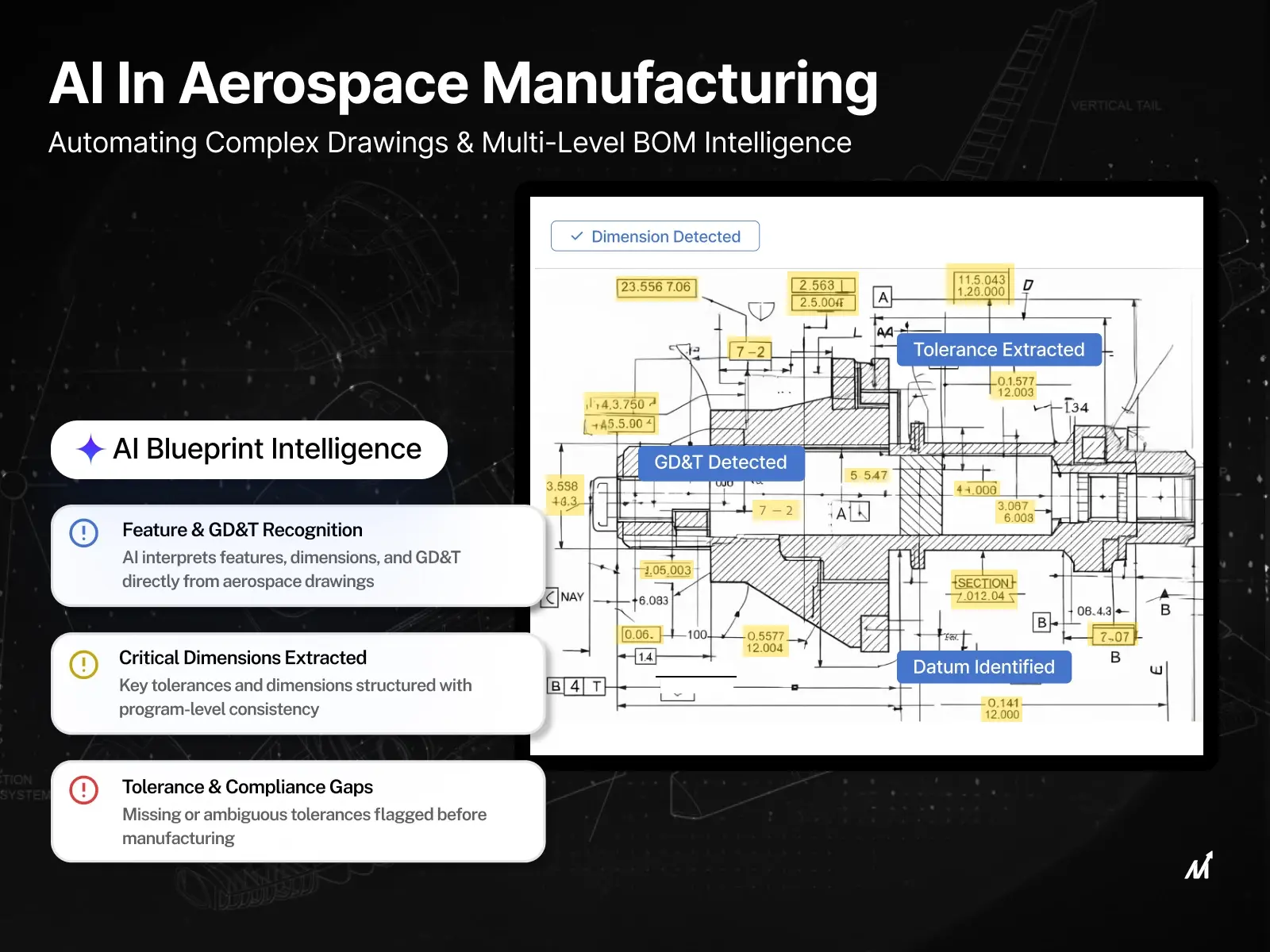
GD&T and datums define how aerospace parts function and fit together. AI can identify these controls and associate them with relevant drawing elements, giving engineers a starting point for verification against the original geometry.
Critical tolerances and datum relationships still require engineering review. The extracted information should be verified before teams use it for machining or inspection decisions.
3. Consistent interpretation across teams and programs
A structured approach to drawing interpretation gives engineering, estimating, and quality teams a common set of details to review. Program-specific standards and customer requirements must still guide how teams interpret those details.
4. Handles scanned, legacy, and mixed-format drawings
Aerospace organizations often manage decades of drawings in different formats, including scanned PDFs, legacy prints, and annotated files. AI can process supported drawing formats and help organize information from existing documents without requiring every file to be recreated as a native CAD drawing.
Automating GD&T Extraction and Feature Recognition with AI Aerospace Engineering Intelligence
Once AI establishes blueprint intelligence, the next critical step is automated extraction of GD&T and features – a requirement for aerospace programs where precision, traceability, and repeatability are non-negotiable.
1. Automated GD&T extraction with program-level consistency
AI identifies and extracts geometric dimensioning and tolerancing directly from drawings, mapping them to associated features and datums.
Teams can use the extracted information to review tolerance requirements against applicable ASME standards, customer specifications, and program-specific rules. The interpretation must still be validated against the relevant standard and drawing revision.
2. Feature recognition aligned to aerospace manufacturing intent
Beyond geometry, AI recognizes manufacturing-relevant features such as holes, slots, pockets, ribs, fasteners, and interfaces. Aerospace drawing feature recognition helps organize these elements in relation to dimensions and annotations rather than treating each shape as an isolated object.
3. Tolerance-to-feature mapping for production and quality workflows
By linking extracted tolerances to recognized features, AI creates a structured basis for machining strategies and inspection planning.
This information can help quality teams identify relevant specifications during review. It does not replace inspection procedures, engineering approval, or formal certification processes.
4. Reduction in interpretation-driven production risk
Missed tolerances, misapplied GD&T, and incomplete feature identification can contribute to scrap, rework, and production delays. Automated extraction can help reduce manual oversight, while engineering review remains important for critical requirements.
5. Scalable accuracy across large drawing volumes
Aerospace programs often involve thousands of drawings across long product lifecycles. AI can help teams process larger drawing volumes using consistent extraction methods, reducing the need for repeated manual review. Results still require validation according to the criticality of the information.
Drawing Intelligence Software Built for Aerospace Engineering Teams
Aerospace teams need more than extracted text. They need drawing data they can review, trace, and use across engineering, quality, and sourcing. Markovate’s drawing intelligence software for aerospace reads GD&T-heavy drawings and turns them into structured data for downstream workflows.
Its key capabilities include:
- GD&T extraction and checks: Reads datum references, feature control frames, and tolerance callouts, and checks drawings against ASME Y14.5 (1994, 2009, and 2018 editions).
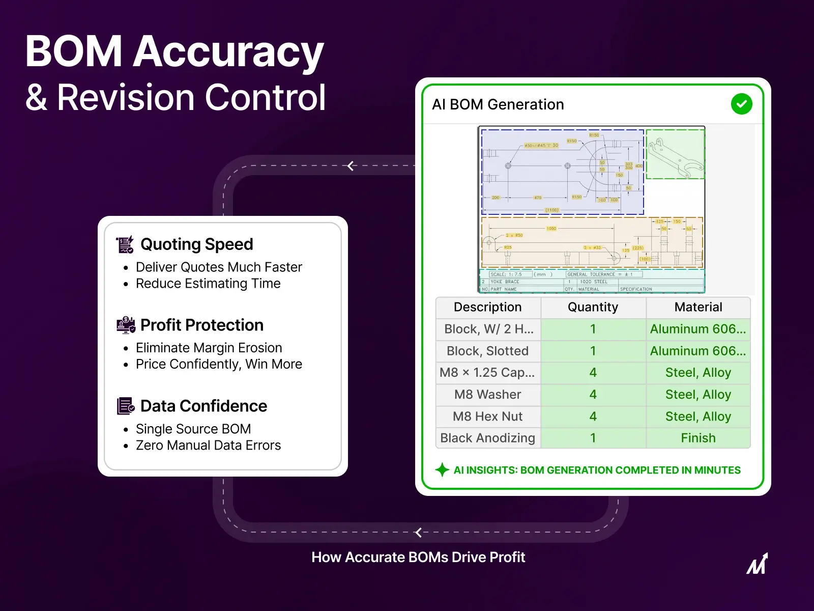
- BOM generation: Produces structured bills of materials with a confidence score on every output, ready for ERP and PLM.
- Quoting and costing: Extracts cost drivers such as material and machining requirements and generates structured estimates that trace back to the drawing.
- Revision and model comparison: Compares revisions to flag dimension, tolerance, and specification changes before release, and validates 2D drawings against 3D models for mismatches and missing or incorrect GD&T.
- Traceability and review: Links each detection to its location on the sheet, records the model and rule pack version, and flags lower-confidence items for quality engineers to review.
For organizations handling restricted drawings, the software can be deployed in a single-tenant, region-locked environment within US-region infrastructure on the Enterprise plan, with EU residency available for scopes outside US controls. Its controlled detection process supports existing quality-management workflows through versioned model artifacts, change-controlled rule packs, and customer-only model training.
Drawing intelligence can also support pre-production workflows, where accurate drawing analysis influences quoting and cost estimation. A customer in precision manufacturing highlighted this impact:
“The automation and accuracy it brought to blueprint analysis have become a major value-add to our pre-production process.” – U.S.-based precision parts manufacturer.
Want to see how this works on your aerospace drawings? Book a demo to explore its capabilities against your drawing requirements.
From Aerospace Drawings to BOMs, Costing, and RFQs

In aerospace manufacturing, drawings are more than design references. They contain information about parts, assemblies, specifications, and cost-related requirements. Once teams have reviewed and organized this information, they can use it in several downstream processes.
1. Automated multi-level BOM generation from drawings
AI can identify parts, sub-assemblies, fasteners, and interfaces across relevant drawing sheets. This information can support aerospace BOM generation by organizing component details and quantities into a structured format for review.
A complete multi-level BOM may also require assembly drawings, parts lists, CAD models, and other engineering records. Teams should validate the extracted structure before using it for procurement or production.
2. Tolerance- and feature-aware cost estimation
Extracted GD&T and recognized features provide useful inputs for estimating machining complexity, inspection effort, and production requirements. These are important drivers of aerospace program cost.
However, drawing data alone cannot determine the final manufacturing cost. Machine capabilities, labor, tooling, production quantities, material prices, and supplier rates also influence the estimate. Estimators need to consider these factors alongside the technical information.
3. Faster, cleaner RFQ preparation for suppliers
Structured BOM information and extracted specifications can make RFQ packages easier to prepare and review. Suppliers can access relevant component details, dimensions, materials, and technical requirements without repeatedly searching through the entire drawing set.
This can reduce avoidable clarification cycles, although suppliers still need to assess production feasibility, capacity, lead times, and pricing before submitting a quote.
4. Improved alignment between engineering, supply chain, and quality
With a shared, machine-readable interpretation of drawings, teams can refer to the same technical details during engineering, procurement, and quality discussions.
This reduces the need to extract or recreate the same information for different functions. Teams can focus their discussions on specifications, sourcing requirements, and issues that need technical review.
5. Scalable support for long-running aerospace programs
Aerospace programs often involve extended product lifecycles and frequent design changes.
Comparing drawing revisions helps teams identify changes that may affect BOM entries, cost assumptions, supplier documentation, or production plans. Teams can then review and update the relevant records through their approved processes.
How Aerospace Drawing Intelligence Fits into Manufacturing & PLM
AI-driven blueprint intelligence is most powerful when it operates within a connected manufacturing ecosystem, not as a standalone tool. In aerospace manufacturing environments, structured drawing data becomes a critical input that strengthens PLM-driven workflows across the entire product lifecycle.
Once drawings are interpreted and structured, that intelligence flows naturally into:
- PLM systems, enriching product definitions with tolerance- and feature-aware data.
- Manufacturing planning, supporting accurate process selection and sequencing.
- Quality and inspection workflows, ensuring alignment with design intent and certification needs.
- Supply chain and sourcing, enabling clearer RFQs and more predictable supplier responses.
Drawing intelligence can also connect with existing systems through structured outputs, APIs, and supported enterprise integrations. The exact data exchange depends on the organization’s systems and integration requirements.
AI does not replace PLM. PLM remains the system of record, while drawing intelligence helps prepare and organize technical information for use within approved engineering workflows.
This gives teams a more practical way to use drawing information across design, production, quality, and procurement without assuming that every downstream record updates automatically.
Conclusion: AI for Aerospace Engineering Drawings
AI for aerospace engineering drawings helps teams interpret GD&T, identify features, and organize technical information across drawing packages. It also supports BOM preparation, cost estimation, and RFQ workflows.
For aerospace manufacturers, reliable drawing analysis depends on more than extracting information. Teams need traceable results they can verify against original drawings, revisions, and engineering requirements.
Markovate’s aerospace engineering drawing intelligence platform focuses on making drawing information easier to trace, review, and use across engineering processes. Contact us to discuss your aerospace drawing requirements.
FAQs: AI for Aerospace Engineering Drawings
1. How is AI used to analyze aerospace engineering drawings?
AI can analyze aerospace engineering drawings by interpreting GD&T, dimensions, features, notes, and part relationships in context. It can convert drawing information into structured data that supports BOM creation, cost estimation, RFQs, and downstream manufacturing workflows.
2. Can AI automatically create multi-level BOMs from aerospace drawings?
AI can extract parts, sub-assemblies, fasteners, and interfaces from relevant drawing packages to support multi-level BOM preparation. A complete BOM may also require assembly drawings, parts lists, CAD models, and other engineering records. Teams should validate the resulting structure before using it for procurement or production.
3. Why is aerospace engineering drawing analysis difficult?
Aerospace engineering drawings often contain dense GD&T, multiple views, revisions, assemblies, annotations, and information on interconnected parts. Manual review can make it difficult to interpret this information consistently across large drawing sets and long-running programs.
4. Can AI extract GD&T from aerospace drawings?
Yes. AI can identify GD&T symbols, dimensions, and datum references in supported drawings. Engineers should verify the extracted information against the original drawing and applicable program standards before using it for manufacturing or inspection.
5. How does traceability help with aerospace drawing revisions?
Traceability connects extracted information to its original drawing location. When teams compare revisions, they can identify changes and review their potential impact on engineering requirements, components, and related documentation.